Intro:
I thought it would be kinda fun to see if I can design and print a completely new and unique object every day for the next week. I'll give myself 24 hours to come up with an idea, design it, and print it. At the end of the 24 hours, I'll post my progress. Whether I've finished or not, I'll move on to a new doo-dad. Realize that I still have a day job, and will probably want to get some sleep, eat, etc. I'll also still be working on some other projects, like the Tricopter yaw motor mount. This will not be an easy challenge. But if it were easy, why do it? : )
Day 1: LED lights for Ikea Lantern
02/04/2015 7:15pm
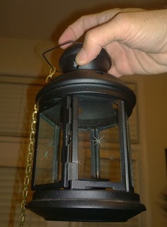
I have this lantern from Ikea that is designed to hold a tealight candle. I'd like to put a coiled up strip of LED lights in it. The LED strip is designed to run off of 12VDC power, but I know from experience that it will actually run off of a 9 volt battery. My plan is to design a cylinder that will house a 9 volt and two AAA batteries that is wrapped by the LED light strip. This would give me 12 volts and maximum burn time. If push comes to shove however, I'm not above scrapping the triple A's and just running it off of the 9 volt.
~~~~~~~~~~~~~~~~~~~~~~~~~~~~~~~~~~~~~~~~~~~~~~~~~~
Below is the design that I created in Google SketchUp for the battery holder. It took me 2:15 to complete this design and slice it with Slic3r for printing. The Pronterface print controller reports that it will take 2:28 to print.
| The piece on the left is the top. I'll just pass some copper wire through it to make battery contacts, and glue it to the body of the battery holder. The battery holder is oriented to be printed upside down, so what you see in the picture is actually the bottom of it. I was able to design it to hold the 9 volt and the two triple A's. The LED strip is going to wrap around this assembly. Based on the height and diameter, it looks like I'll have about 72 LED's wrapped around it. The bottom cover will be held in place with two 3mm screws. I have no switch for this thing, and since it's a 24 hour challenge, I'm likely to just use the ends of the wire, twisted together to close the circuit as a switch. I'll decide tomorrow if I can do anything better. | 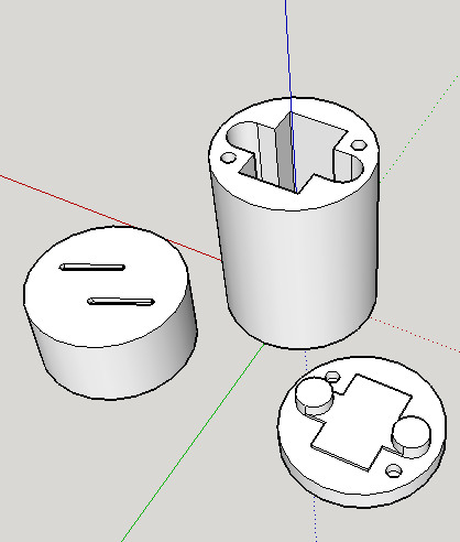 |

2/5/2015 12:35am
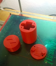
Doo-Dad for day 1 is complete. I made a few mistakes that needed to be resolved in order to make it work. First, the 1mm holes for the wires to pass through didn't actually print. They are too small for the resolution of the printer. I had to drill the holes manually after the parts were printed. I'll make them 1.5mm next time around. Second, the slots for the wires on the top were in the wrong position. I was looking at the holes from the bottom side when I made the slots. If I had done them correctly, the lower slot in this picture would have been to the left of center, and the upper one to the right. I fixed it with my Xacto saw. Third, I didn't make any accommodation for the wires to connect to the battery ends. I filed a couple of groves in the end of the case for the wires to pass through when the cover is in place. I also had to file a little off of the edge of the post that holds the AAA battery for its wire to pass. Fourth, I made the screw holes for the battery cover too large and the 3mm screws had nothing to thread into. It didn't really matter because the wires created a pretty nice friction fit for the cover. Next time, I'll make the holes 3.4mm diameter instead of 3.8mm. Finally, I didn't have a switch. But this was also easily taken care of by simply using the battery cover to press the wires onto the battery ends when the cover is installed. I think it's worth mentioning that I had a near miss with the super glue that I used to stick the top onto the body. There was a little dried up blob of glue in the tip of the nozzle. I was squeezing the tube when the dried glue popped out and a big gush of glue came out. Most of it landed on the part, and a little went onto the back of my hand. I just rinsed it off of my hand without touching it, and after the little bit that was left dried up, I took it off with a little acetone. Although this thing didn't turn out perfect, the design file could easily be updated if I wanted to produce something people would want. Success.
Doo-Dad for day 1 is complete. I made a few mistakes that needed to be resolved in order to make it work. First, the 1mm holes for the wires to pass through didn't actually print. They are too small for the resolution of the printer. I had to drill the holes manually after the parts were printed. I'll make them 1.5mm next time around. Second, the slots for the wires on the top were in the wrong position. I was looking at the holes from the bottom side when I made the slots. If I had done them correctly, the lower slot in this picture would have been to the left of center, and the upper one to the right. I fixed it with my Xacto saw. Third, I didn't make any accommodation for the wires to connect to the battery ends. I filed a couple of groves in the end of the case for the wires to pass through when the cover is in place. I also had to file a little off of the edge of the post that holds the AAA battery for its wire to pass. Fourth, I made the screw holes for the battery cover too large and the 3mm screws had nothing to thread into. It didn't really matter because the wires created a pretty nice friction fit for the cover. Next time, I'll make the holes 3.4mm diameter instead of 3.8mm. Finally, I didn't have a switch. But this was also easily taken care of by simply using the battery cover to press the wires onto the battery ends when the cover is installed. I think it's worth mentioning that I had a near miss with the super glue that I used to stick the top onto the body. There was a little dried up blob of glue in the tip of the nozzle. I was squeezing the tube when the dried glue popped out and a big gush of glue came out. Most of it landed on the part, and a little went onto the back of my hand. I just rinsed it off of my hand without touching it, and after the little bit that was left dried up, I took it off with a little acetone. Although this thing didn't turn out perfect, the design file could easily be updated if I wanted to produce something people would want. Success.
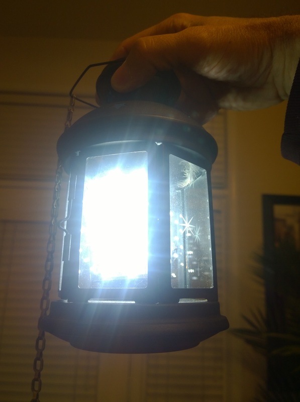 LED insert for Ikea Lantern | 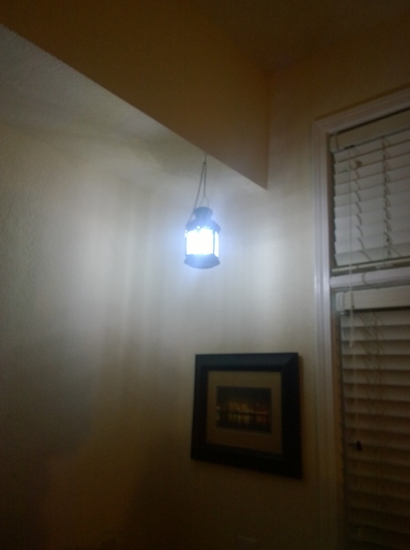 #Abstract2Actual 5:20 |
2/8/2014 Post build update:
I modified the design to include an on-off switch and posted it on Thingiverse as thing 673491.
I also posted the instructions on Youtube as"Ikea ROTERA light package"
I modified the design to include an on-off switch and posted it on Thingiverse as thing 673491.
I also posted the instructions on Youtube as"Ikea ROTERA light package"
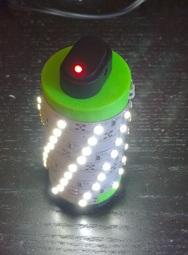 LED light package w/rocker switch #Abstract2Actual 6:05 | |

 RSS Feed