Abstract2actual
  • Home
  • Blog
  • Gallery
  • Buy stuff
  • Contact
  • About

Programming the Adafruit PiTFT buttons

8/28/2016

0 Comments

 
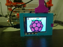
After installing the Adafruit PiTFT display to my Raspberry-Pi, I wanted to use the buttons on the panel.  I searched high and low for examples of this, but couldn't find what I was looking for.  Ultimately I want to use one switch to port the display back and forth between the HDMI monitor and the TFT display and another switch to switch the wireless from a LAN configuration to an ad-hoc configuration.  I found a nice article that teaches the basics of using switches connected to the GPIO header here. https://www.cl.cam.ac.uk/projects/raspberrypi/tutorials/robot/buttons_and_switches/  This was really helpful in developing the script I wound up building.
​
I'm still having trouble figuring out how to call the framebuffer and network using a script, so I chose to takle something a little simpler, just to prove the concept of using the buttons to execute Pi commands.  The TFT has a backlight that can be turned on and off, and there's a program called OctoPiPanel that can pretty easily be called by a script, so these are what I chose to control.  I programmed the third switch to simply output a line of text to the terminal indicating that the switch had been pressed and what state the toggle was in.

I found a reference at https://github.com/jonaslorander/OctoPiPanel that showed me how to run OctoPiPanel.  Once I had it installed I had to get the Octoprint API key and copy it to the OctoPiPanel.cfg file.  Then I had to make OctoPiPanel executable.  From that point, I can launch OctoPiPanel from a command line which I will later tie to one of the switches.

The next step was to create a python script that monitors the buttons.  it uses RPi.GPIO to map the switches.  I added some logic to create a two state state engine, so I can essentially treat each switch as an on-off switch even though they are only momentary.  I mapped one switch to start and stop OctoPiPanel and another switch to toggle the LCD backlight.  Finally, I modified the startup script /etc/rc.local to call my monitoring script.
Now I can toggle the backlight and run OctoPiPanel at the press of a button.

I published my work on GitHub here:  https://github.com/TJEmsley/PiTFT-Button-Monitor
0 Comments

Raspberry Pi Display Upgrade

8/24/2016

0 Comments

 
Picture
I've been successfully using a Raspberry Pi as a host controller for my Airwolf3D v5.5 since April of last year.  See my previous blog post about setting that up.  I really like that setup, but I want this rig to be more portable, and lugging around a 14 inch flat screen isn't very helpful there.  My awesome girlfriend bought me an Adafruit 2.8 inch PiTFT touchscreen for my birthday last year, and I finally got the nerve to set it up.  The installation was fraught with failure.  Mostly because of my lack ​​of attention to detail, and in part due to the scattered nature of the instructions.  This project consisted of 3 phases: hardware assembly, software installation & configuration, and designing a new case.  I'm not going to count unit testing, redesign, or user acceptance because any project manager worth their salt knows that these things just magically get done.

I used the Adafruit site as a reference but it's not exactly intuitive, as both the simple automagic installation and detailed installation instructions run together, so I wasn't really sure where to start.  I chose to follow the detailed instructions, just so I'd understand what was going on.  My first attempt was successful, but in trying to figure out how to get the desktop to boot to the new display, I blew everything up and had to re-image the micro SD.  Fortunately, I keep a copy of the last known good image on my laptop, so it only took 5 minutes to get the Pi back to its original state.  Installing the display software the second time was easier, but I accidentally clicked a link for the capacitive touch display instead of the resistive touch display and set the wrong configuration settings.  Third time's a charm, but I still couldn't get the desktop (X windows) to boot to the new display.  Thank Google for helping me eventually find it, buried in the instructions that I was looking at on the Adafruit site.  It was listed under "extras" in the installation instructions.  Ultimately, here is how I got this to work:
Hardware assembly part 1
Solder the tactile switches onto the PiTFT module
Software installation & configuration
​NOTE: Start with a raspberry pi that has a working install of Raspbian with network access.  Mine had the latest Octopi image.
Open a terminal window and execute the commands in bold text below:
Make sure it the Pi is up to date
    sudo apt-get update
Download the kernel
    curl -SLs https://apt.adafruit.com/add-pin | sudo bash
install the kernel
    sudo apt-get install raspberrypi-bootloader
Edit /boot/config.txt file to add device tree overlay
    sudo nano /boot/config.txt
    and add these lines at the end of the file
        [pi1]
        ​device_tree=bcm2708-rpi-b-plus.dtb
        ​[pi2]
        ​device_tree=bcm2709-rpi-2-b.dtb
        ​[all]
        ​dtparam=spi=on
        ​dtparam=i2c1=on
        ​dtparam=i2c_arm=on
        ​dtoverlay=pitft28r,rotate=90,speed=32000000,fps=20
    Save the file and exit

    sudo shutdown -h now
    Now install the TFT on the Pi and power it back on.  There won’t be anything on the TFT display yet, but we will test it now.
    Open a terminal window and run these three commands
    sudo mv /usr/share/X11/xorg.conf.d/99-fbturbo.conf ~
    export FRAMEBUFFER=/dev/fb1
    startx
If you did everything right, you should see the Pi desktop on the little display now.  :)

​Now we have to send the display back to the HDMI monitor to finish the work so open a terminal window in the little display and execute the following commands
    export FRAMEBUFFER=/dev/fb0
    startx
The desktop should now appear on your regular monitor
Now we’ll add support for the touchscreen  Open a terminal window and edit the module list
    sudo nano /etc/modules
        Add the following line at the end of the file
        stmpe-ts
    Save the file and and exit
Reboot by entering the following command
    sudo reboot
After the Pi reboots, check to make sure that the modules installed.  Open a terminal window and enter the following command
    dmesg
Somewhere in that message, you should see the below lines
Picture
Create a calibration configuration file
    sudo mkdir /etc/X11/xorg.conf.d
    sudo nano /etc/X11/xorg.conf.d/99-calibration.conf
    enter the following lines
        Section "InputClass"
        Identifier      "calibration"
        MatchProduct    "stmpe-ts"
        Option  "Calibration"   "3800 200 200 3800"
        Option  "SwapAxes"      "1"
        EndSection
    Save the file and exit
Try sending the desktop  to the new TFT again
    FRAMEBUFFER=/dev/fb1 startx
If you did it right, the display will show up on the new TFT :)
Send the desktop back to the big monitor so we can finish the work
    FRAMEBUFFER=/dev/fb0 startx
Make the it so startx defaults to the TFT by editing the ~/.profile
    sudo nano ~/.profile
    Add this line near the top of the file
        export FRAMEBUFFER=/dev/fb1
    Save and exit the file
Enable booting X windows (the desktop) to the TFT by moving a file and editing it.
    sudo mv /usr/share/X11/xorg.conf.d/99-fbturbo.conf ~
    sudo nano /usr/share/X11/xorg.conf.d/99-pitft.conf
       Add the following lines
        Section "Device"
        Identifier "Adafruit PiTFT"
        Driver "fbdev"
        Option "fbdev" "/dev/fb1"
        EndSection
    Save the file and exit
If you want to use the left tactile switch as power off/on, edit the /etc modules file
    sudo nano /etc/modules
    Add the following line at the end of the file
        rpi_power_switch
    Save the file and exit
Create or edit the adafruit config file
    sudo nano /etc/modprobe.d/adafruit.conf
    add this line to the end of the file
        options rpi_power_switch gpio_pin=23 mode=0
    Save the file and exit
Make the switch active by running the following command
    sudo modprobe rpi_power_switch
If you press the left most switch on the display board, the pi should shut down.
Press the button again and the pi should boot to the TFT display

NOTE: ​If you ever want to run the display on the HDMI just open a terminal and enter the following
    FRAMEBUFFER=/dev/fb0 startx

Design and print the case

I desighed the case in Sketchup and made it available on Thingiverse as thing 1737249.
I printed the body on my Airwolf3D v5.5 and the covers on X3REX, my modified Prusa i3.
The design resolves the problem I've had with the micro SD slot on the Pi.  It's a springloaded slot, but the catch on the spring no longer works, so the card will not stay seated.  THe clip on the left side of the case not only holds the case together, it keeps the card in the slot.  I designed and printed the case, and found that the fit wasn't quite right, so with a few tweaks I fixed the alignment problems and re-printed.  v2 of the case came out just right.  I still have to work on the mast for the camera.  I want it to fold down and out of the way while the unit is in transport.

Hardware assembly part 2
Install the Pi and TFT in the case. 
Raspberry Pi TFT case.  #Abstract2Actual 3 days, 6 hours, 27 minutes
0 Comments

Goodbye Kapton Tape

8/24/2016

0 Comments

 
I've said goodbye to Kapton tape after having used on my heated printbeds for the last 3 years.  I have to admit, it works really well for keeping ABS parts stuck to the bed, but it isn't cheap and after a while it tears or buckles.  These tears and buckles cause the surface to look crappy.

I peeled off the tape on X3REX, my modified Prusa i3, then coated the glass with ABS dissolved in acetone.  I set the bed temp to 100 C, put an enclosure around the printer, and added a 4mm brim to the slicing profile.  The results were great.  The bottom surface was really clean and smooth, no warping, and once the bed cooled, the parts just fell off the glass.  With Kapton tape, I usually had to pry the parts off which can damage parts or hands trying to do the prying.  I also peeled the tape off of my Airwolf3D v5.5 and had good results there too.

The parts I printed were of uniform thickness, so I may be jumping to conclusions about the effectiveness of this method, as parts with varying thickness have more of a tendency to warp.   I'll let you know if things change.

Kapton tape works great, and I think it's especially helpful when you first get into printing since you have less warping to deal with.  But once you get the basics down, I believe you can do without this expensive consumable.  
0 Comments

Jazzy's Hammer

8/7/2016

0 Comments

 
Eight year old Jossilyn created a toy hammer for her sister Jasmine.  Using SketchUp, she designed it by first creating a cylinder, then adding a rectangular shaped handle.  One of the things I love about SketchUp is that you can design something without worrying about details like dimensions.  Jossilyn's original design was a hammer that was over four meters in diameter, with a handle that was something like 11 meters long.
Picture
Picture
Jossilyn can focus on design, having only to ensure that the proportions look correct.  She doesn't need to measure anything, and free of that burden, she can simply design.  She put a lot of thought into her design, and although you may not see it very clearly here, she thought to rotate the handle about 90 degrees so that it would be easier to hold.  You can download the design file from Thingiverse.

After I got the file, I simply used the SketchUp scale tool to reduce it to 10% of the original size.  I also separated the handle from the hammer head so that it could be printed without support.
Print time for this was 6 and a half hours.  I sliced it with .4mm layer height, and printed it on my modified Prusa i3, X3REX.  
I did two other things with this print, that I haven't done before.  First, I removed the Capton tape from the heatbed and printed directly on the glass.  The tape was buckling and torn, causing annoying textures on the surface touching the printbed. I coated the glass surface with a lot of "goo", which is simply ABS dissolved in acetone, to hold the parts to the printbed.  I also put a cardboard enclosure around the printer to prevent warping and layer separation.  There was only a little warping on the handle, about .2mm on either end.  I saw a few separated layers, but it was negligible.  The parts came off the bed really easily.
​
Best of all, Jasmine loved the toy that her sister created for her!
0 Comments

Octoprint time lapse on Z axis change

8/4/2016

0 Comments

 
I printed a bunch of bulldog collars for a guy in Switzerland. This batch took about 8 hours to print on my Airwolf3d v5.5 printer.  Using my Octopi host controller, I took a time lapse video using the option to take a frame on each layer change rather than at timed intervals.  I hadn't tried this method before now, but I'll definitely do again because it looks so cool.  The result is a 10 second video where the printed parts appear to be rising up out of the print bed.
0 Comments
    View my profile on LinkedIn

    TJ Emsley

    Lifetime tinkerer.

    Archives

    October 2022
    January 2021
    November 2020
    October 2020
    September 2020
    February 2018
    January 2018
    January 2017
    October 2016
    August 2016
    July 2016
    June 2016
    May 2015
    April 2015
    March 2015
    February 2015
    December 2014
    October 2014
    August 2014
    July 2014
    May 2014
    April 2014
    March 2014
    November 2013
    October 2013

    Categories

    All
    3d Design
    3d Printing
    Open Source

    RSS Feed


Proudly powered by Weebly