Abstract2actual
  • Home
  • Blog
  • Gallery
  • Buy stuff
  • Contact
  • About

IT's been way too long.

10/30/2022

0 Comments

 
My latest project, the "Name Your Own Price Gun" (NYOPG) has just been completed, but before I get into that, I'd like to summarize some major stuff I've done since I last posted, a year ago. 
The Prusa i3 upgrade is still not complete.  I have the dual hot ends, but haven't built the extruders.  I do need to get that done because I want a one printer that uses 3mm filament. 
I also overhauled the old Airwolf v5.5, which involved replacing the Gen6 motherboard with a RAMPS4.4, adding an LCD display controller, replacing the 3mm Wades Extruder and hot end with a 1.75 Bowden extruder and Phaetus Dragonfly hot end.  The Airwolf prints better than ever.
I also bought a Creality CR30 Printmill belt printer.  It worked great for the first 30 days or so, then something got out of whack with the alignment and I'm having trouble getting parts to adhere to the bed.  I'll have to do some research to figure out how to fix that.  Now, on to the NYOPG.
The idea came up because Sonya, my wife, wanted to have a Halloween costume party and she decided to dress as Flo from the Progressive insurance commercials.  With that costume in mind, I searched online for images of the famed prop.   The only one I could find was a tiny thumbnail sized image, but it gave me enough to go on.
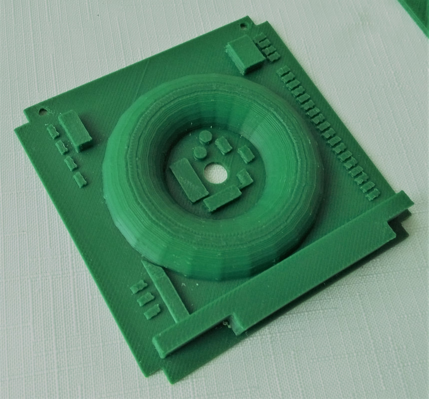
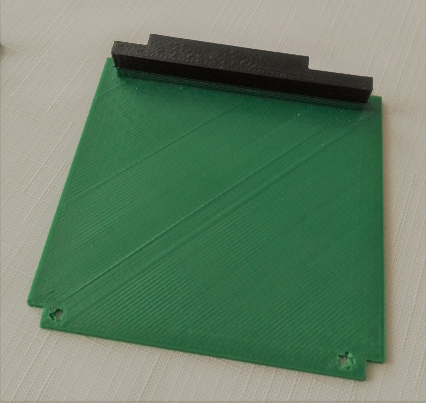
I went to work in Sketchup, first building a monolithic model.  I decided I wanted the trigger to be functional so that you could squeeze it and when you release it, it would spring back into place.  I had to break the monolithic model into parts so that I could come up with such a functional trigger.  I separated the pistol grip from the body at first, then decided I could split the body in two parts, drop the pistol grip into the lower half, install the trigger, and screw the top half on to hold everything together.  The pistol grip needed a trigger cavity, so I carved that out, then separated the trigger as an individual part.  To capture the spring, I designed a block with a hole in it that sat down in the back of the trigger cavity.  I sliced it all in Slic3r and sent everything to my Airwolf 5.56 printer.  Printing time was just over 16 hours for all the parts.
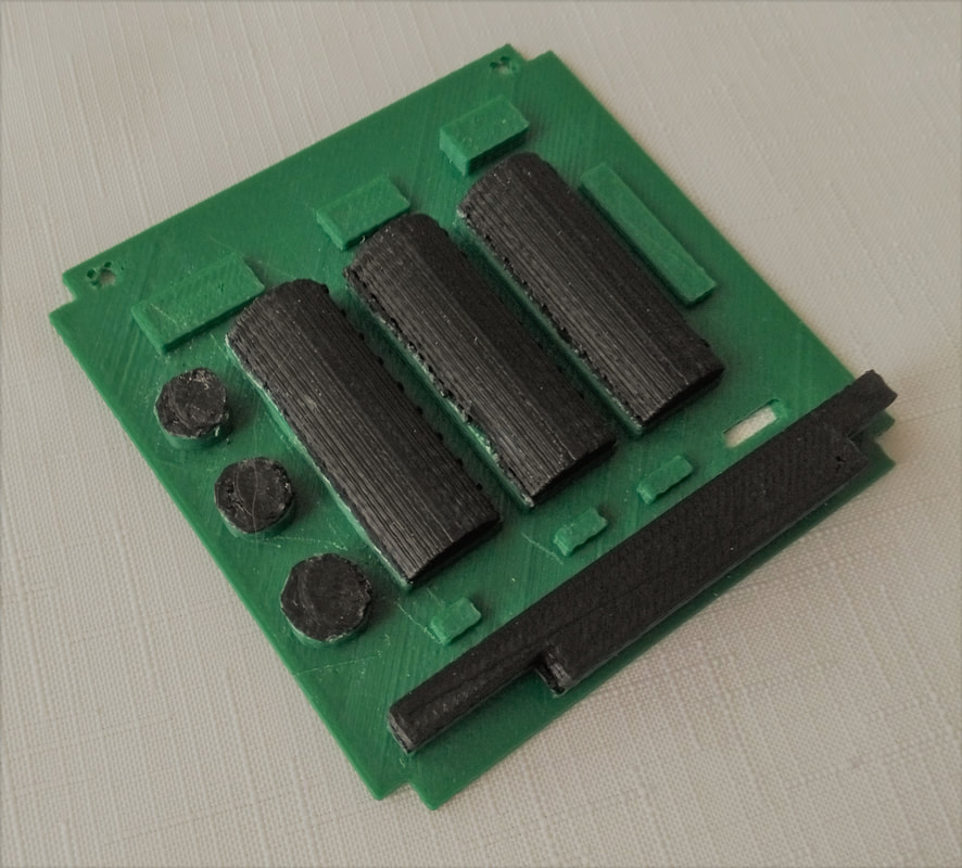
When I went to assemble everything, I found that there was no way to install the trigger spring.  I ended up cutting the block in half along the spring hole so that I could install the trigger, push it forward, insert the lower block, insert the spring, and then put the upper block in to capture the spring, which worked really well.  with the trial and error, assembly time was just over an hour. I decided to paint it to match the web image, and I really didn't like how that turned out.  The paint had a tendency to run along the layer lines and, even though I masked everything off, it looked rather sloppy.  The other issue I had was that I didn't have the "Progressive" logo on the side.
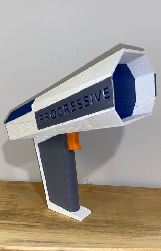
I went back to the model and scaled it down 15% because the original seemed obnoxiously large.  Then I separated the parts even further so that I could print it in the four colors I needed.  I ended up with 14 parts for the final iteration which can be screwed and/or glued together.  The total design time was 11 hours, 43 minutes.
I decided to print half of the new design on my X3REX modified Prusa i3 and the other half on the Airwolf 5.56  Print time on the X3REX was 8:16 for all of the white components and the Airwolf ran for 6:23 printing the color parts.  This assembly took a lot more time, about 3 hours and a lot more glue, but it turned out pretty good.  I wouldn't call it commercial quality, but definitely a good costume prop.
The design is posted on Thingiverse, however I have trouble opening the page there.  Let me know if you have trouble with the link and I'll post another way.
Picture
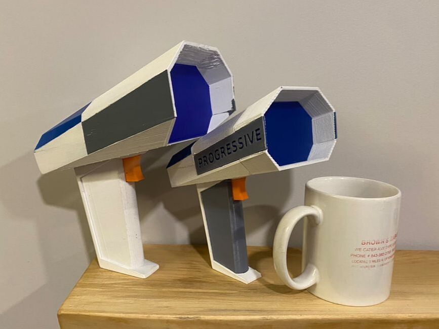
Prototype, final iteration, and coffee mug for size
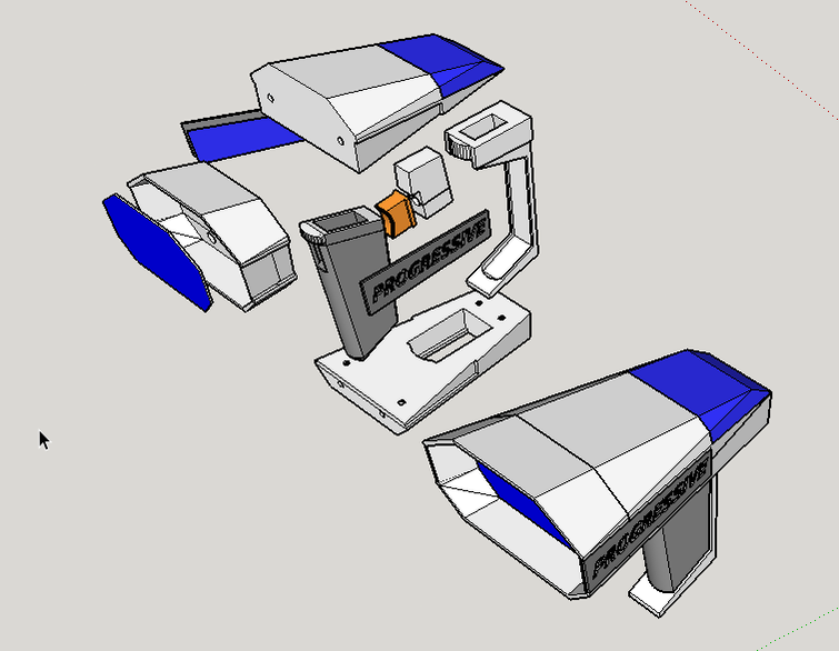
Picture
Exploded view
Picture
#Abstract2Actual 1 day, 6 hours, and 16 minutes (over the course of 5 days)
0 Comments

Major Overhaul of the Prusa i3

1/4/2021

0 Comments

 
  My Prusa i3 has been limping along for over a year.  I replaced the hot end heater resistor, which worked, but it was a little smaller than the original and took a lot of current to heat up.  There were also issues with the heated bed thermistor and missing steps in X and Y axis.  It seemed the perfect time to overhaul the machine, and while I'm at it, convert the hot end from a single Wades extruder to a dual Bowden extruder.  I've never worked with a dual extruder, so I had to do some studying in advance.  Frankly, there's a lot of reasons NOT to have dual extruders, but in the worst case, I just don't use the second extruder.
So far, it has not been as straightforward as I had hoped.  The first problem that came up was that I had no copy of the Marlin configuration files from the original build.  Ugh!  I'd have to figure it out all over again.  The next issue I had was that the original Arduino IDE installed on my computer was sorely out of date.  When I updated to the new Arduino App for Windows 10, the libraries weren't compatible and every time I tried to compile Marlin in Arduino, it failed.  After much research, it seems that the Arduino App on Windows 10 just won't reliably compile Marlin.  The solution was to download the Visual Studio Code IDE with the PlatformIO and Auto Build Marlin add-ins.
Sadly, this didn't immediately resolve the problem, but it did provide very detailed logs that helped me figure out what was wrong.  And I had a lot of things wrong.  I entered decimal numbers for stepper motor counts when only whole numbers are allowed.  I also selected the default motherboard "MOTHERBOARD BOARD_RAMPS_14_EFB" which was barfing on the second extruder settings.  It turns out that EFB stands for Extruder Fan Bed, and a dual extruder machine is EEB (Extruder Extruder Bed).  I fixed all that and finally got the Marlin to build and load onto the printer.
Since I was doing all this, I decided to also replace the original A4988 Pololu stepsticks with DRV8825 drivers.  The DRV8825s are odd because the trimmer pot is on the opposite end of the board than the A4988, and the direction you turn the pot is also opposite.  Another thing was that the pots were turned all the way up to the max, so the stepper motors got really hot as soon as I turned them on.
The next issue was calculating the step counts for the stepper motors.  While the Prusa step count calculator was correct for the Z axis, it was pretty far off for the X and Y axis.  This was compounded by a very high max feed rate and homing feed rates. It took me half a day to get the driver current, step counts, max feed rate, and acceleration settings.
After all of that, I decided to tackle another problem where the LCD was blank.  I thought that I probably had the wrong display selected in the Marlin configuration file, but a little research lead me to the contrast setting on the display board.  It only took a little tweak to fix that.
The controller fan wasn't working either after loading Marlin, which was also just a matter of a couple of lines in the configuration_adv.h file.
Things I have left to do:  configure the extruder fans, wire up the extruders, build the cold ends for the Bowden extruders (waiting on the drive gears), mount the heat bed thermistor and run a few calibration prints.

0 Comments

New Video Platform

11/9/2020

0 Comments

 
I found a new video platform, Rumble.com today.  I'll be posting my video content there. :)
0 Comments

Chicken Waterer Mod

10/2/2020

0 Comments

 
I was having trouble with my chicken waterers. The buckets all eventually crack where the threads of the watering nipple pull against the thin wall of the bucket. I designed this contoured plate that goes on the inside of the bucket so that the nipple threads engage the plate rather than the bucket.
Instead of the recommended 11/32 (9mm) holes, I drilled the bucket with slightly larger 7/16 (11mm) holes so that the nipple threads won’t engage the bucket, just the plate. The plate evenly compresses against the bucket wall and the exterior gasket.

I designed this using both Sketchup and OpenScad.  I like Sketchup because it is a graphical user interface.  However, the default circle tool is not high enough resolution to accurately represent the curve of a five gallon bucket, so I started by creating a high definition cylinder in Openscad, and exporting it as an STL.  From there, I imported the file into Sketchup and modified it to create just a small plate with the hi def curve. The design is published on Thingiverse as thing 4262960.

NOTE: This needs to be used with a new bucket. It does not repair cracks, but it will prevent the new bucket from cracking.
#Abstract2Actual : 55 minutes

0 Comments

Upgraded to Raspberry Pi 4 Model B

9/30/2020

0 Comments

 
      After four years of running OctoPi on my Raspberry Pi 2, I decided it was time for a hardware upgrade.  There's really nothing wrong with the old machine, except that I'm a few versions back on Octoprint because I've been reluctant to upgrade Python.  Having a new machine gives me the ability to play around with the new stuff without losing the basic capabilities I currently have.  The upgrade was a bit tedious because the original PiTFT package for the power off button is no longer available.  Of course I didn't find that out until after I disassembled the old Pi. The good news is that the PiTFT installation is a lot simpler thanks to the upgraded drivers from Adafruit. It turns out that I didn't need the power off package, because I was able to leverage the python script for the buttons.  Below the slide show, you can read how it all went down.
       I bought a brand new Raspberry Pi 4 Model B (2Gb), PiCam v2-8 Megapixel camera module, heatsink kit, and USB3 cable from Amazon.  There are some differences between the Pi 4 and Pi 2 that I noticed right away.  First, the board layout and external connections are very different, so the old case was not going to work.  I also noticed that the Pi 4 runs quite a bit hotter than the Pi 2, so I ordered a cooling fan.  I wanted to connect the fan to GPIO pins 2 & 6, but the PiTFT takes up the lower 2/3 of the GPIO so I also had to get a 26 pin flat ribbon cable to take advantage of the output jack on the bottom of the PiTFT.  I cut off all but 4 of the wires on the ribbon cable, leaving wires for pins 1, 2, 4, & 6.  I'm only using 4 and 6 to power the fan, but kept 1 & 2 in case I find a use for 3.3v and 5v power in the future.  I soldered the red fan wire to pin 4, and the black wire to pin 6. and plugged the connector into the PiTFT output jack.
      I modeled a new case in Sketchup that accommodates the Pi 4B connectors, the fan, and a folding camera mast.  The case also needed vents which I created in 3D text with the name of my big printer, X3REX. I blinged it up by turning the hole in the "R" into a D and I printed that in a contrasting color, just for fun.  I also liked the idea of yellow and magenta, as if it's radioactive. Routing the fan wires to prevent them from hitting the fan took a few attempts and changes in the case design, but ultimately, I got them out of the way.  The new case design is available on Tingiverse.   I assembled everything and got ready for the software installation.
      I chose to just download a system image from Octoprint.org as the basis for this project. Just follow the installation instructions on the Download page to create the bootable microSD card and configure the network.  I put the SD card into the Pi and booted it up and was happy that no smoke came out.  The Octoprint image is for a headless system, so there was just a login prompt on the display.  I plugged in a keyboard and mouse, logged in, and moved on to install the PiTFT drivers.  As I stated in the opening paragraph, it was much easier than it was 4 years ago.  Since the operating system is already installed, you can jump down to the Installer script section of the Adafruit PiTFT Easy Install page.   The installer walks you through display selection, screen rotation, and if you want to the console to appear on the PiTFT rather than HDMI output.  If you mess this up, don't worry, just run the script again and choose the correct configuration.
      Getting the tactile buttons to work was a whole different story since the Adafruit site doesn't have any information on this any longer.  Fortunately, I had that in my earlier blog post, so I simply copied the python script and updated the /etc/rc.local file to run it at boot up.  But it didn't work! I took a look at the file and saw that it was trying to execute  os.system("sudo sh -c \"echo '0' > /sys/class/gpio/gpio508/value\""),  which was not a valid command.  I went back to the Adafruit site, digging deep into the PiTFT support documentation and found a page on Backlight Control.  Here i found that turning on and off backlight was accomplished with sudo sh -c 'echo "1" > /sys/class/backlight/soc\:backlight/brightness' .  I replaced the lines in my original python script with these lines, and button 3 on the PiTFT now switches the backlight on and off.  Since the original power down script no longer worked, I edited button 1 in the python script to execute sudo halt.  The new python script and instructions are available on my GitHub project.
0 Comments

Printing with Nylon

2/4/2018

0 Comments

 
It's been a long time since I messed with Nylon filament, but I needed an example of different materials for something I'm trying to get going at work. I had really good success with Taulman Bridge at 250C and the bed heated to 45C.  I coated the glass plate with Elmers glue and didn't have any trouble keeping the part adhered to the bed.  When it cooled off it popped right off.  I sliced the part using a spiral mode, so there were no retractions which made for a nice clean part with no Z seams.  
0 Comments

More work on the city of Charlotte

2/4/2018

0 Comments

 
I've continued work on my Charlotte, NC city model and now have about 60 hours into it.  I have 10 buildings done and I made this 3 minute video in SketchUp to show the progress.  Although my camera skills could use some work, you get an idea of how things are shaping up.  I've still got some work to do on the top of the Bank Of America building. 
​The goofy little cylinder I have on top is just a place holder until I can figure out the detail.  I borrowed a couple of cars from the SketchUp warehouse because they look kinda cool.
0 Comments

Some updates to the 1U CubeSat model

1/22/2018

0 Comments


The A2A 1U CubeSat is representative of the pinnacle of crowdsourced agile engineering.

​The Main Board is loosely based on the now defunct open source fractal encabulator.  Otherwise, the board is comprised of commercially available off the shelf components including the nofer trunions.  Even the most elementary students of encabulation will notice the conspicuous lack of hydrocoptic marzel vanes which, aside from exceeding LFM mass limitations, would be completely useless in the vacuum of space. The sole function of the Main Board is to handle any event of sinusoidal deplaneration.  When this occurs, the lunar wayne shaft is engaged to facilitate a forescent score maneuver to prevent bit fumbing.
Picture
Picture
​The micro CERN isometric particle accelerator with tuned ejection port provides primary propulsion at scale.  It is capable of producing 6 braleys per terrex in the lateral and longitudinal planes whereas rotationally, the output is a logarithmic tangent of the inverse.  A series of concentric ductile plenums conjoined with gribbley collets in an atypical trapezius configuration ensure translational and rotational alignment of particles immediately preceding ejection port engagement.  Particle malignancy beyond the distal facia is negligible


​​Professional engineers and amateur enthusiasts alike will appreciate the inclusion of a fully customizable circuit card with the standard prefamulated ammulite substrate.  With its PC104 form factor, creation of monolithic circuits tailored to mission objectives has never been easier. 
Picture
Picture


​​System power is provided by an advanced quark capture amagulator master power unit (MPU).  Bosons passing through the triplet of IEC R6 cells regenerate the cathode through ionization, providing an extended MPU lifespan. Converse redundancy in this configuration, eliminates the requirement for onboard ancillary power units (APUs).  


​
​I do want to take a moment to thank my good friend Rick Lavin at the Dragon Moonshine Company in Charlotte , NC for first introducing me to the genius of the Encabulator.  


To learn more about the fascinating technology behind the Rockwell International turbo encabulator, check out the youtube video in the link to the left.
0 Comments

Printing the city of Charlotte

1/7/2018

0 Comments

 
, After printing the Dallas model, Sonya wanted to know if I could print our own home city, Charlotte, NC.  I looked online for models and there are none, so I am going to design and print it from scratch.

​Starting with a satellite view of the city from Google maps I'm using SketchUp to model the buildings .  I made a screenshot of the city and imported the .jpg into SketchUp.  From there I can outline the base of the buildings and pull the model up out of the outline.  I am referencing skyscraperpage.com for building heights, then using Google maps and Bing maps satellite and street views to get details for the buildings.

I spent about 8 hours on the first building, the Westin hotel and then about 6 hours on the new Regions Bank building next to it.  Later I spent about 7 hours on the Duke Energy Center building, where I work.  Next to it is the Mint Museum, and Museum Tower apartment buildings which took me another 6 hours.  I then decided to tackle One Wells Fargo Center which took me about 14 hours.  What made it so difficult was that it is about 1 degree off of the X-Y axis in Sketchup and I didn't realize that one of the walls was automatically snapped to the green axis.  When I got to the top of the building, it wasn't symmetrical, so I basically had to tear it all down, find the stray line and rebuild it all.

Although it isn't a skyscraper, the Bank Of America stadium is a significant landmark in the city that I want to include in my model.  For this, I got a very zoomed in satellite image to base it on.  When I tried outlining the building in SketchUp, I found that my lines were not staying on top of the picture, which meant I couldn't see where one line ended to connect the next line.  Not knowing what to do, I "exploded" the .jpg image of the stadium and then my lines layed on top of it just fine.  I was in for a real surprise when I pulled the building up from the base because the image remained on the extrusion.  I was not expecting this at all.  I thought the extrusion would simply be the basic white material in SketchUp.  Then when I started manipulating the surfaces , I found that the image stuck to those too.  The result of 7 hours of design work was this really cool looking model below, which took about an hour to print
Picture
Picture
I published the BOA stadium model on Thingiverse HERE if you want to print one yourself
0 Comments

Printed the city of Dallas

1/1/2018

0 Comments

 
My son TJ II saw a 3D printed miniature of the city of Dallas and wondered if I could print it for him.  He had a link to the creators website ​​http://www.3dprintedskylines.com/  The creator was also kind enough to publish the design file n Thingiverse HERE.  Of course I wanted to print a really big model, around 18 inches from end to end. Scaling up the original model from Thingiverse was easy, but it was not easily chopped into seperate printable sized pieces, so I spent about 40 hours cleaning up the file.  I then seperated it into seven printable sized chunks and sent them to my X3REX modified Prusa i3 printer.  I also published my remixed design files on Thingiverse HERE.  After 48 hours and 38 minutes of printing and about 800 grams of ABS filament I have this really cool looking model
Picture
Dallas (only bigger) scale model: #Abstract2Actual 3 days 16 hours 38 minutes
0 Comments
<<Previous
    View my profile on LinkedIn

    TJ Emsley

    Lifetime tinkerer.

    Archives

    October 2022
    January 2021
    November 2020
    October 2020
    September 2020
    February 2018
    January 2018
    January 2017
    October 2016
    August 2016
    July 2016
    June 2016
    May 2015
    April 2015
    March 2015
    February 2015
    December 2014
    October 2014
    August 2014
    July 2014
    May 2014
    April 2014
    March 2014
    November 2013
    October 2013

    Categories

    All
    3d Design
    3d Printing
    Open Source

    RSS Feed


Proudly powered by Weebly